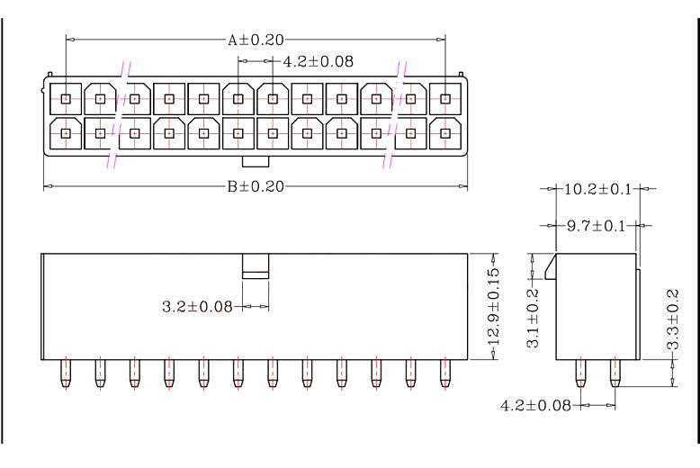
20+ terminal block diagram
For this reason we can employ regulators like a Zener transistorized otherwise 3-terminal integrated regulators. The internal resistors act as a voltage divider network providing 23Vcc at the non-inverting terminal of the upper comparator and 13Vcc at the inverting terminal of the lower comparator.

C4 Urs4 S6 Starting Circuit Audiworld Forums
This satellite communication system can be explained through three blocks namely uplink transponder and downlink where these components of the satellite communication system their working are discussed below.

. Hover your mouse click on any product to learn more. The different parts that make up your cars engine consist of the engine block cylinder block the combustion chamber the cylinder head pistons the crankshaft the camshaft the timing chain the valve train valves rocker arms pushrodslifters fuel injectors and spark plugs. Lugs 40 AWG Cable 38 Ring.
A terminal block sometimes called junction block is a convenient connection point for two wires. Hence it is connected to the negative terminal of the power supply. Drivers Seat Heating Module Passengers Seat Heating Module Terminal 15 Power-Saving Relay Rear Left Seat Heating Module Rear Right Seat Heating Module.
Very small aperture terminal networks. Terminal 87 1 Terminal 87 3 vehicles with a gasoline engine. The circuit block diagram of the switching power supply is as follows.
Front-passenger door power window switch terminal 302 SAM signal acquisition and actuation module 25. Terminal and harness assignments for individual connectors will vary depending on vehicle equipment level model and market. Industrial controls design specialists including schematic wiring diagram bill-of-materials wire fromto list and panel layout since 1988.
The block diagram of the satellite communication system includes the following. Swine influenza virus SIV or swine-origin influenza virus S-OIV refers to any strain of the influenza family of viruses that is endemic in pigs. Mercedes-Benz Sprinter w906 fuse box diagram Pre-fuse box at the base of the drivers seat only for auxiliary battery F597.
Working Principle Refer Block Diagram of 555 timer IC given above. Block Diagram of Switching Power Supply Circuit. Interactive electrical wiring diagram for DIY camper van conversion skoolie RV.
An SMPS-switched mode power supply can be used for supplying huge load current by small power. The voltage of Uo2 is short-circuited to the ground. 12 V socket center console for.
The engine block is the main part of an. Once you are finished configuring your task click the OK button. Experienced with DIN IEC AS and US.
Terminal Block 4 to 20 Gang Rated 500 out of 5 625 3950. Your data will be available on the data output. Connect to Bus Bar Terminal Fuse Block and Battery Pack of 2 1.
Given below is the circuit diagram of switching voltage regulator using LM 2575. Pin 20 GND This pin is connected to the ground. This saves your settings and returns you to your block diagram where you will see your configured DAQ Assistant Express VI.
Connect to distribution panel Pack of 3 1. You can wire this output to an analysis VI file IO VI directly to an indicator etc. AutoCAD Electrical training courses and training material including on-site.
SRB starter relay fuse and relay module NAFTA Vehicles with code XM0 Starterfor electrical supply support using the additional battery. Brake system ABS 5. Pin 21 to Pin 28 Port 2 Pin 21 to pin 28 are port 2 pins also referred to as P20 to P27.
Diesel engine engine componentscontrol unit vehicles with a natural gas engine NGT 2 10. A Versatile Building Block for Micropower Digital and Analog Applications Phase Comparator II Output Terminal 13 Phase Pulse Terminal 1 NOTE A. Swine influenza is an infection caused by any of several types of swine influenza viruses.
8 CD4046B Phase-Locked Loop. 92CS-20011R1 Signal Input Terminal 14 VCO Output Terminal 4 Comparator Input Terminal 3 VCO Input Terminal 9 LPF. Dashed line is an open-circuit condition.
A voltage regulator in the regulated power supply is essential for keeping a steady DC output voltage by supplying load regulation as well as line regulation. Terminal Block and Negative Bus Bar. Terminal 87 6 1 10.
Negative Bus Bar 10 Circuit 1800. This IC is known for its high efficiency and will clearly replace all 3-terminal linear voltage regulators. Nissan Sentra fuse box diagram fusible link block battery.
A pulse applied to this terminal resets the whole timer irrespective of any input. Z3 breaks through the control terminal of the SCR1 SCR1 gets the trigger voltage so the SCR is turned on. SRB starter relay fuse and relay module 3.
Lugs 14 AWG Cable 10. Luggage Compartment Charging Socket Centre Console 12V Socket. It has to be provided with 0V power supply.
LM 2577 switching voltage regulator circuit diagram is given below. Output Overvoltage Lockout Circuit. Electrical Computer-Aided Design Consulting for AutoCAD AutoCAD Electrical 2017 ToolboxWD VIAWD and Promis-e.
As of 2009 identified SIV strains include influenza C and the subtypes of influenza A known as H1N1 H1N2 H2N1 H3N1 H3N2 and H2N3. The high efficiency of the IC can be obtained even without a heat sink. Terminal 87 1 Terminal 87 3 vehicles with a gasoline engine.
4th Generation Town And Country Wiring Diagram The Chrysler Minivan Fan Club Forums
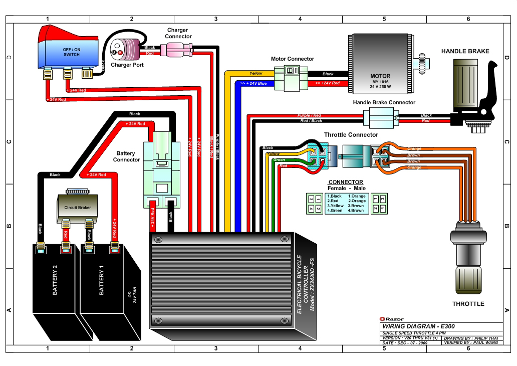
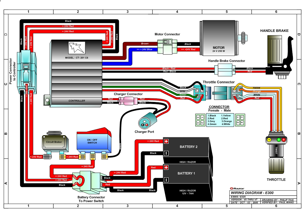
Razor E325 Electric Scooter Parts Electricscooterparts Com
Atx And Pci E Power Supply Connector Guide

Pin Assignment Of Db15 Connector Download Scientific Diagram

Changing From 10dn Alternator To Si Team Camaro Tech
Atx Power Supply Pinout And Connectors

A Maker S Guide To Atx Power Supplies 6 Steps Instructables

Complete Stereo Wire Diagrams All Stereos Navigation 8th Generation Honda Civic Forum
Audio Wiring Diagrams 9th Gen Civic Forum
1955 Chevy Color Wiring Diagram Chevy Tri Five Forum
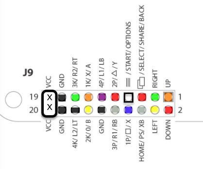
20 Pin Joystick Button Harness Focus Attack

A Maker S Guide To Atx Power Supplies 6 Steps Instructables

Toyota Car Radio Stereo Audio Wiring Diagram Autoradio Connector Wire Installation Schematic Schema Esquema Car Audio Pioneer Car Audio Car Audio Installation

Electrical Wiring Question Extra Connectors Can Am Maverick Forum

Complete Stereo Wire Diagrams All Stereos Navigation 8th Generation Honda Civic Forum
Power Supply Connectors And Pinouts
Razor E325 Electric Scooter Parts Electricscooterparts Com